PODILSKY BRIDGE CROSSING OVER RIVER DNIPRO IN KYIV
Chief Project Engineer of arch bridge over river Dnipro Ph.D., M.Korniiev
Podilsky bridge crossing consist of combines auto and metro viaducts and three big bridges. Total length of viaducts is about 3.6 km. As part of the bridge crossing there five bridges across water obstacles: 2 road bridges and 3 combined road-metro bridges - through Desenka, Harbor of Dnipro and arch bridge with the span 344 m across the Dnipro river.

Fig. 1 Scheme of arrangement of structures. Section along the axis.


Fig. 2 Scheme of arrangement of structures. Plan.
In this time, only two bridges are completed: road bridge over Dnipro Harbor and combine road-metro bridge over Desenka river.

Fig. 3 Overall View of the Harbor Bridge in Kyiv, 2009.

Fig. 4 Combine road-metro two-level bridges over Desenka River. 2009
ARCH BRIDGE OVER DNIPRO IN KYIV. GENERAL INFORMATION

Fig. 5 Overview of Arch Bridge over Dnipro in Kyiv

Fig. 6 Superstructure Cross section of Arch Bridge
General information shown on Fig.6 and Fig.7. Scheme - 64+344+64=472 m. Total weight 15960 t; relative weight 0.969 t/m2 per top deck (girder 9 650 t., arch 6185 t., cables 125 t). Concrete of the piers 40 500 m3. Design Bureau of Mostobud started to develop the design drawing of bridge in 2005 and completed in 2007. Construction works started in 2005 and carried out normally until 2009, then slowed, and by 2012 almost stopped financing. Now actually stopped financing.

Fig. 7 Overview of Arch Bridge from Google Map

Fig. 8 Photo from right bank
ARCH BRIDGE OVER DNIPRO IN KYIV. ORTHOTROPIC DECKS AND TRUSSES


Fig. 9 View of truss from bottom level
Truss-girder include two levels. Top level for roadway and bottom level for rail transport metro. Also, on the bottom level located 3 big-diameter pipes (boiler and cold water line). Total weight of this pipes more, then metro load.
ORTHOTROPIC DECK FOR ROADWAY
Orthotropic deck for roadway performed with closed trapezoidal ribs with a wall thickness of 8 mm. Steps of longitudinal ribs 600 mm (300 mm bitewing the walls of ribs). The thickness of the sheet deck 14 mm. Step of crossbeams 4.0 m. Due to the fact that the farm in cross section has a frame structure, the force of suspend have a significant effect to crossbeams (see Fig. 10).

Fig. 10 Typical deformation of cross frame in section of suspend
Big shear force create a big stresses in the wall of crossbeams. Typical stress in the crossbeam shown on fig. 11.

Fig. 11 Typical stress in the crossbeam in section of suspend
Assessment of fatigue for the roadway orthotropic plate was investigation at several points, as shown in Fig. 12. Fatigue assessment performed using fatigue-library in EN 1993-1-9, but with the counting the number of cycles in future 100 years of bridge service.

Fig. 12 Points, for assessment of fatigue for the roadway orthotropic plate
ORTHOTROPIC DECK FOR METRO
Orthotropic deck for rail transport have the original structure. This orthotropic have two box ribs upper of the sheet of plate, as shown in Fig. 13, 14 and 15.

Fig. 13 Bottom rail orthotropic plate. Scheme.

Fig. 14 Bottom rail orthotropic plate. Photo

Fig. 15 Bottom rail orthotropic plate. Dimensions.
Fatigue assessment performed using fatigue-library in EN 1993-1-9, but with the counting the number of cycles in future 100 years of bridge service, as roadway deck. Assessment of fatigue for the roadway orthotropic plate performed at several points, as shown in Fig. 16.

Fig. 16 Points, for assessment of fatigue for the railway orthotropic plate

Fig. 17 Diagonal bracing element
Diagonal element have box cross sections, but in the part of joint, we have H-type section as shown in Fig. 18 to simplify the joint.

Fig. 18 End of diagonal element

Fig. 19 Cross section of arch
The cross section of the arch was subject not only for structural reasons, but also for architectural reasons. To do this, the surface of the wall have the relief.

Fig. 20 View of erection element of ½ arch
ARCH BRIDGE OVER DNIPRO IN KYIV. ROPES
Suspensions was made of locked coil strand and have two sockets. Top side is a cylindrical socket with throat surface and nut. In the bottom side located the fork socket.

Fig. 20 Suspension of the locked coil strands

Fig. 21 Ropes at the timber table

Fig. 22 Anchoring structure in the bottom deck.

Fig. 22 Side view
ARCH BRIDGE OVER DNIPRO IN KYIV. ERECTION
Assembling the erection section with the length 80 m and weight 700-750 t executed at a high-level slipway on the left bank of Dnipro. On the next step, erection section extends over the water, loaded on a floating pier and transportation to the temporary piers.

Fig. 23 Floating pier for transportation the erection section

Fig. 24 Erection arch section by floating crane


Fig. 25 Temporary hinge for arch
The hinge scheme passed the self-weight of arch. Thereafter, the hinge is closed and all other weight apply in arch without hinges.
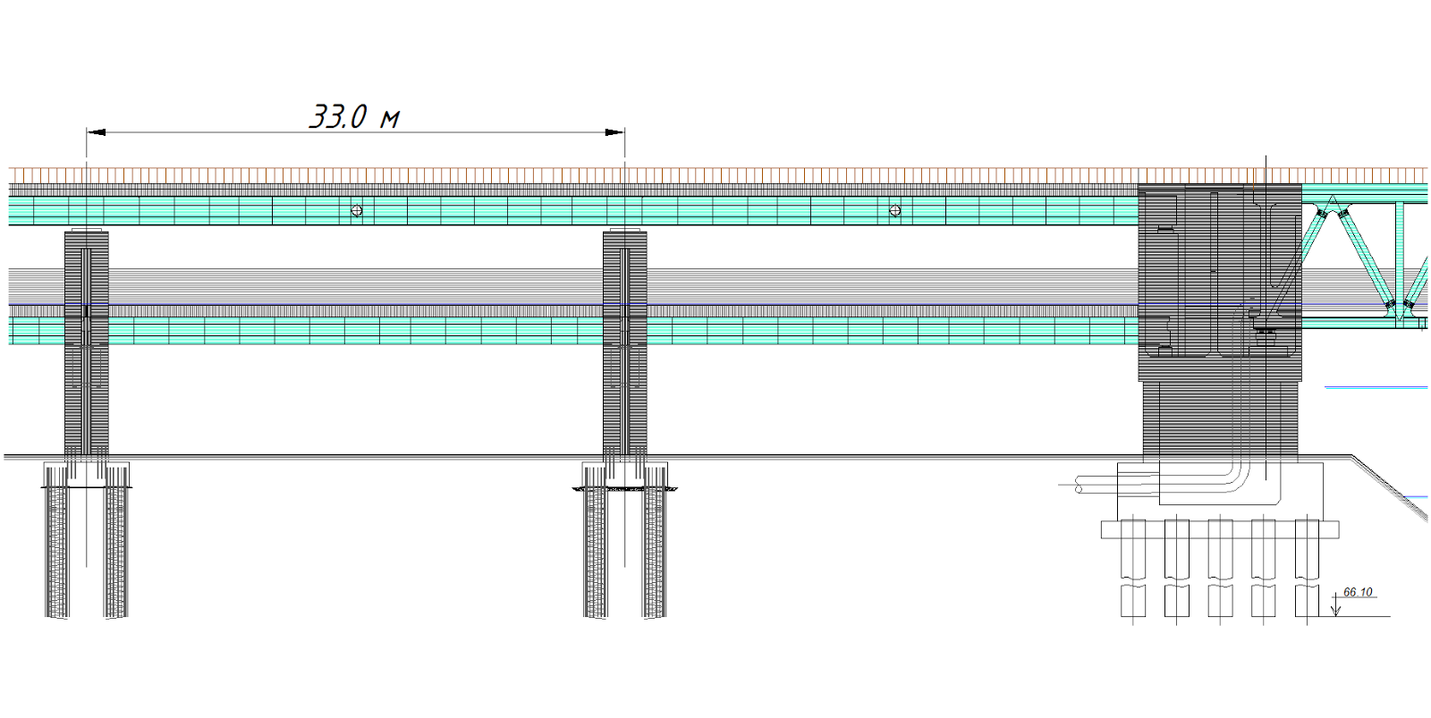
COMBINED ROAD AND METRO TWO-LEVEL VIADUCTS ON APPROACH
The total length of viaducts with the span 30-35 m more than 7 km in both directions. All viaducts – composite steel and concrete. On the top level, superstructures for roadway applied without crossbeams. Volumes: steel C390 – 0.15 t/m²; concrete – 0.28 m³/m².

Fig. 26 Cross-section of Podilsky combined viaducts.
On the bottom level, superstructures for metro has the volumes: steel C345 - 0.21 t/m²; concrete - 0.26 m³/m².


Fig. 27 View of combined viaducts and steel structure of Metro beam.
VIDEOS
OTHER PICTURES


Комментариев нет:
Отправить комментарий